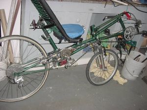
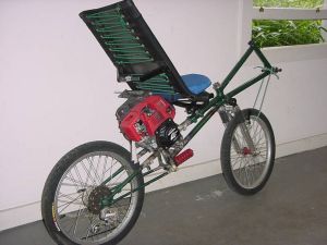
The completed mid drive now sans front derailleur. I'm now using 2, 5-speed freewheels. 25 gears seems plenty.
Jim's home | HPV home | This bike's home
The completed mid drive now sans front derailleur. I'm now using 2, 5-speed freewheels. 25 gears seems plenty.
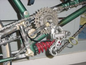
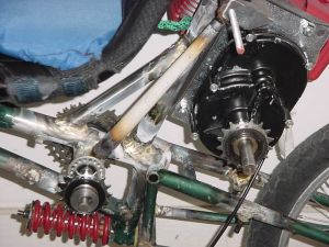
A close up of the mid drive. Mounting the derailleur in a sturdy way was tricky. It also has to be able to swing out of the way for removal of the jackshaft.
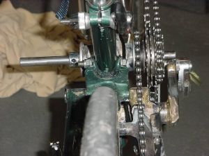
Looking down on the mid drive. You can see the track cog to the left of the freewheel with its chain continuing back to the rear wheel, and the shaft extending out the left side of the bike.
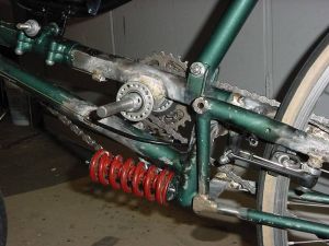
A view from the left side. The motor's drive chain will drive the shaft extending out the left side visible here. The shaft fits through sealed bearings pressed into wheelchair hub flanges that fit into the bottom bracket shell I brazed onto the recumbent's main tube.
The conversion was entirely successful. Shifting improved in fact. Shifting with two rear derailleurs is a little bizarre. Since the jumps between cog sizes is similar between the front and wheel freewheels, the only reason to shift with the front vs. the back shifter (for pedalling purposes, not power assist) is to avoid running out of available cogs on either freewheel. I seem to take turns, shift once on the front, then the back, etc.
On to Step Two
With complicated and labor intesive step 1 now finished, it was time to move on to step two, mounting the engine. I sent my GX31 to Staton Inc and had them mount the gear reducer on it, and bought a bunch of small parts to make things easier. They sandwiched a steel plate between the gearbox and the clutch housing for mounting the engine. I welded together some angle iron to make a mounting bracket that bolts to the steel plate.
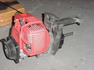
The engine with mounting bracket. It basically hangs from the two tabs with holes, allowing it to pivot and tension or de-tension the drive chain.
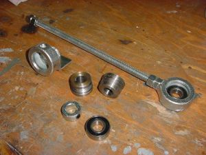
Small parts from Staton Inc. A threaded rod to adjust tension between the drive cog on the gear reducer and the cog on the bikes mid drive. Also bearing casings made from shaft collars and some custom machined freewheel mounting pieces that fit on a 5/8" shaft.
And Step Three
Making the angle iron mounting fixture was complicated enough to warrant being called step 2, so step 3 was to build the structure that the angle iron mounting fixture bolted on to. This required removing the telescopic tube which allowed my recumbent seat to recline by varying degrees. It had to be triangulated for sturdiness too. Here's what I came up with.
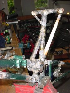
Triangulated tubes. I also brazed a short chunk of tube below the bottom bracket shell to the tube below to stiffen the frame overall.
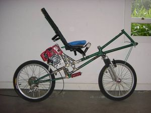
Side view of the motor on the bike. Not much clearance. I measured with the suspension fully excercised so hitting a bump wouldn't make the rear wheel hit the motor.
Another view from the rear. The engine mount bolts onto the bike's triangulated tube structure by a threaded rod with locknuts.
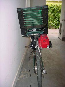
Rear view. Despite the engine seeming to be more to the right side, it'll actually be pretty well balanced with the weight of the gear reducer and the threaded rod, bearing casings and bmx freewheels and chain.
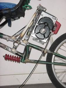
Side view of the motor mounted. You can see how it'll be able to swing to tension and de-tension the chain. That cable hanging off is the throttle cable.
The two bmx freewheels on their respective shafts.