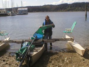
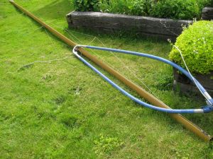
Rigging for launch on that fateful day.
Jim's home | Trimaran home | Best Guess home

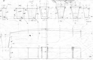
Plans for the center hull. People have asked me for plans for this boat. Besides crude, quick little sketches, this is all I have. I drew it on an 11"x17" piece of tracing paper in 3/4" scale. It provides the critical stuff, like the scoop and rocker shape on the bottom, the width at various points (both top and bottom), and the placement of the bulkheads. In retrospect I might make the bottom surface of the back end a little wider to promote earlier planing, and subsequently add a bit more volume in the tail. This shape was based on a windsurfing slalom board.
Unfortunately I don't have photos showing how this center hull (vaka) was built. But these below show laminating the fiberglass over the structure.
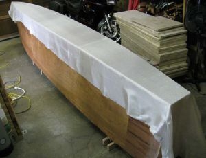
Fiberglass cloth laid over the bottom before laminating on with epoxy. I used Raka brand epoxy with their non-blushing hardener.
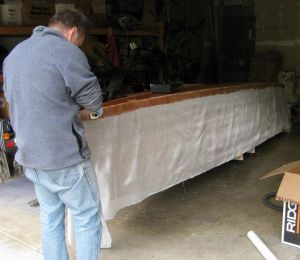
Laminating glass onto the sides with a bristled roller.
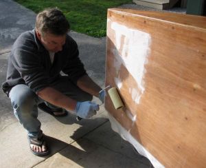
Almost done with one side.
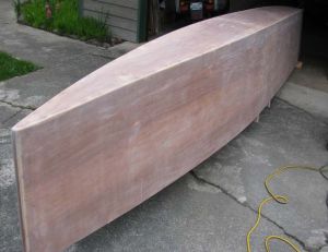
All glassed and sanded.
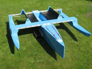
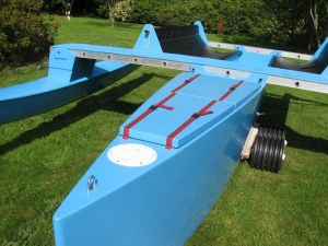
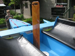
View from above. Plenty of seating around the cockpit, but people can walk on or hang out on the front aka. It's covered in plywood and coated with sugar-textured epoxy. Lots of seating!
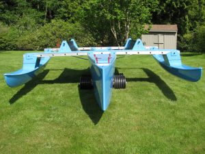
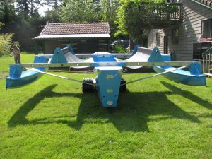
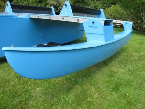
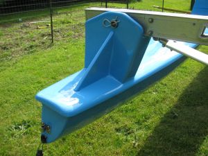
Frontal view, sitting on dolly.
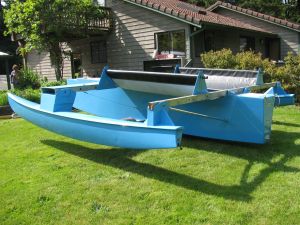
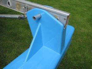
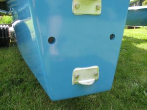
Decent view of bow scoop with the intent for a planing center hull.
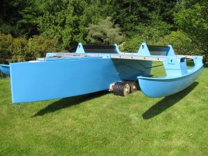
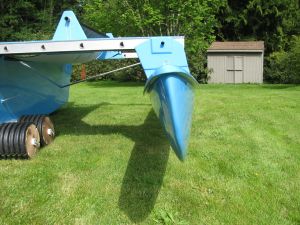
Rear side view.
Rear view.
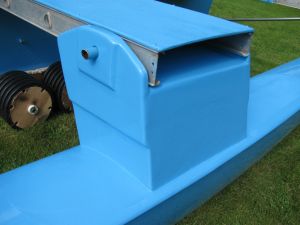
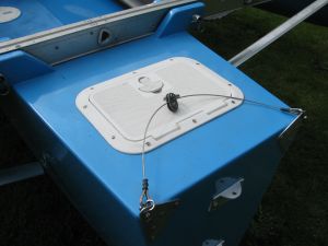
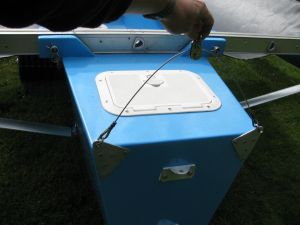
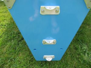
Front deck view showing bow u-bolt for tethering the bottom of the jib, removable hatch cover for far forward compartment (to isolate damge in the event of a crash), and storage compartment covers secured with polypropelene straps and nylock snap buckles.
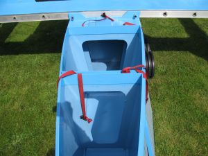
View inside the storage compartments. They're pretty cavernous.
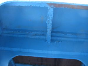
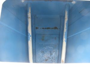
View from inside a storage compartment, looking up at the reinforcement below where the mast will seat.
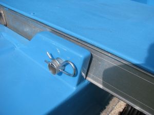
Detail view of plywood/fiberglass flanges that secure the forward aka with a pin made from 1" aluminum tubing. A large cotter pin secures the aluminum pin. There are 3 layers of plywood and 5 layers of fiberglass in this flange.
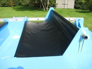
Seating made from heavy duty, waterproof truck tarp vinyl. The back support tube is a section of a skinny, carbon fiber windsurf mast. It'll never break. Both the back support tube and the rail of the hull are covered in foam so seating at the shoulders and behind the knees is soft and comfortable. I tested different recline angles and felt that this should be optimal for relaxing while sailing. This is much lighter than plywood and glass seating would have been.
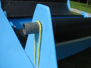
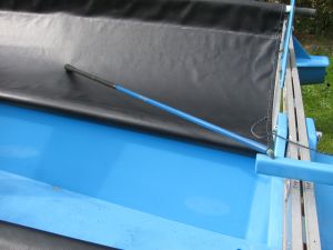
Bungie material secures the carbon tube back supports.
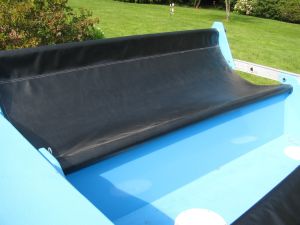
Another view of the seating.
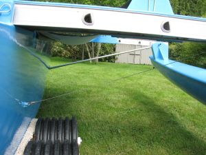
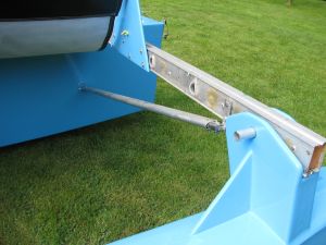
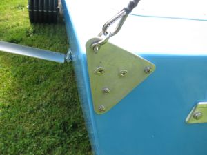
A stainless steel cable is used for a water stay on the forward aka. Cable stays from the mast will attach to the top sides of the forward aka forming a diamond shape of cables, supporting the forward aka from upward and downward forces. A rigid aluminum tube is used to support the rear aka since there will be no cable pulling upwards on it.
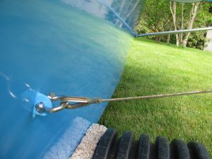
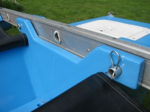
Detail of water stay cable attachment to center hull. The stainless steel tang protruding from the hull is 1" x 1/6" stainless steel plate that extends from one side of the center hull to the other, and bolted to a bulkhead with stainless steel bolts and locknuts.
Hobie 14 hull used for ama.
Plywood/fiberglass/epoxy boxes built to connect amas to akas. The bulkheads extend down into the hulls and are laminated to the hull walls. Plywood increases from one to three layers in thickness as it extends from the lower area to the area around the pin hole.
Plywood/fiberglass/epoxy structures to connect the rear of the amas to the rear akas. One inch end grain balsa wood panels were used to fill in the space between the two plywood bulkheads.
Aluminum faired hang glider down tubes were used for the rear aka support struts. They pin to stainless steel strap extending across the rear section of the amas.
Plywood/fiberglass/epoxy structures to connect the rear of the amas to the rear akas. One inch end grain balsa wood panels were used to fill in the space between the two plywood bulkheads.
Aluminum faired hang glider down tubes were used for the rear aka support struts. They pin to stainless steel strap extending across the rear section of the center hull.
The back end of an ama, with the structure used to connect it to the rear aka.
View of ama showing how it's angled outwards. The intent was that it be vertical when the boat is heeled over.
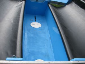
The cockpit footwell. Sugar-textured epoxy coating at the bottom. Two access hatches allow for inspection of and access to the space below the plywood floor.

A detail view of the daggerboard slot. Foam stick-on tape used to make friction for the daggerboard when inserting and retracting. Electrician's gray plastic conduit lines the pin holes for durability.
The rear aka pinned to bulkhead flanges. Again, three layers of plywood at the top of the bulkhead with 5 layers of fiberglass.
The deck near the stern. A hatch allows access to this compartment. The stainless steel cable traveler allows the tiller to pivot underneath.
Pulley for traveller.
Aluminum plate anchoring cable traveller to transom.
Triple gudgeons at transom made from angle aluminum. I didn't trust just two. And yes, I made the pintels three different lengths so it's easy to set the rudder.
Drain holes at transome. PVC pipes run from rear of cockpit floor out the transom. Hopefully the cockpit floor will be above the waterline.
A view into the rear compartment just forward of the transom. PVC drain pipes from the cockpit visible here, along with pieces of plywood used to splice the hull skin sections together.
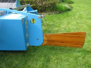
The cedar strip daggerboard in retracted position. I may shorten this after seeing how low the sail hangs after setting the rigging.
Cedar strip retractable rudder.
Tiller extension made from cross country ski pole, wrapped in bicycle handlebar tape, epoxied to tiller with climbing rope.
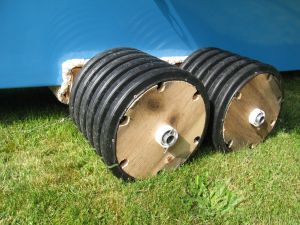
Dolly made from plastic drainage pipe for wheels, galvanized 1" conduit for axles, PVC pipe for bearings, carpet coverd treated 2-by wood for frame. Works great!
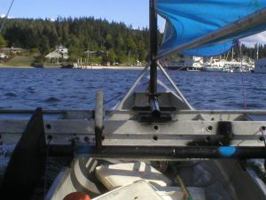
I used the windsurfer boom to make a rig similar to a Nonsuch sailboat. No vang or traveller needed. No boom at the bottom to hit you in the head. Easy to adjust sail tension too.